Drive Units
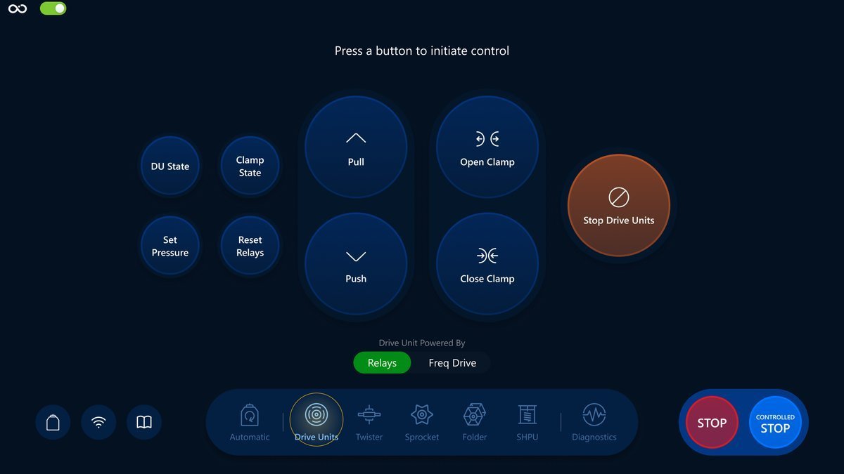
In this section we will have a closer look at how you can use the Drive Units screen to control the system during the CPT operation in Manual Mode.
Navigation
Choose the Drive Units icon in the navigation bar for navigation:
Controls
We will have a look at a brief description of the controls, their responsibilities and also how it reflects on the Visualization screen.
DU State
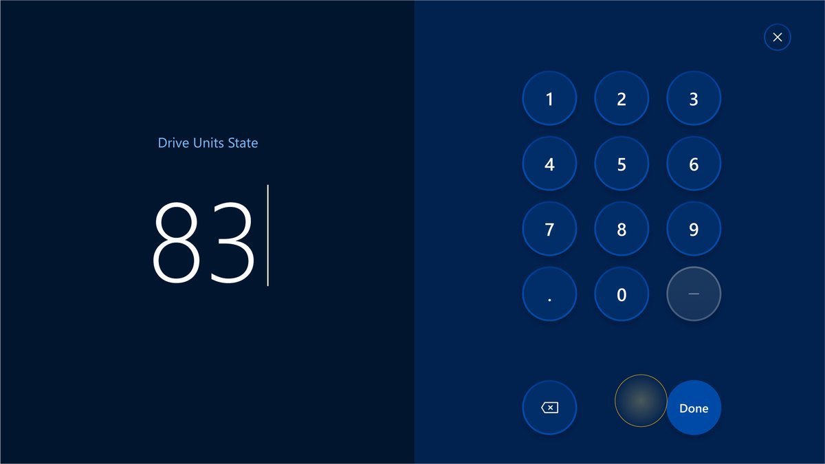
Opens a modal where an operator can set the Drive Units State.
The button:
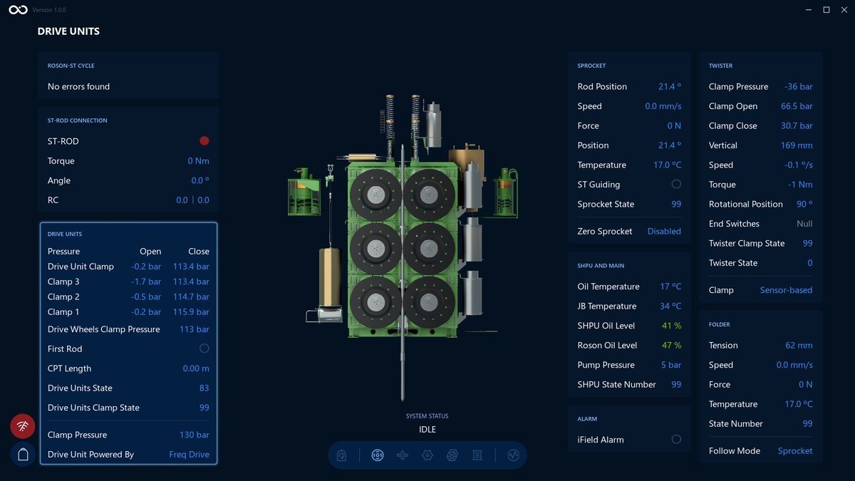
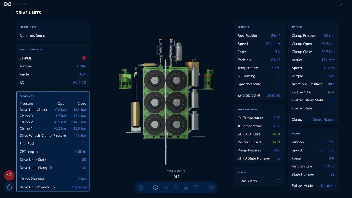
An example of the Visualization screen after changing the value for Drive Units State to 83. We can see the Drive Units State value changed and highlighted on the bottom left side:
Set Pressure
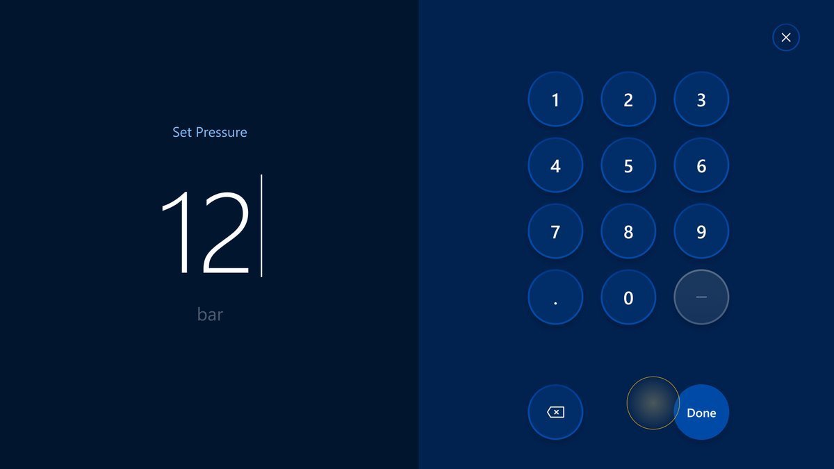
Opens a modal where an operator can set the clamp pressure.
The button:
An example of the Visualization screen after changing the pressure value to 12 bar. We can see the Clamp Pressure value changed and highlighted on the bottom left side:

Clamp State
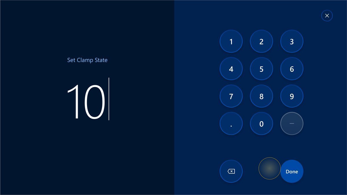
Opens a modal where an operator can set the clamp state.
The button:
An example of the Visualization screen after changing the value for Clamp State to 10. We can see the Drive Units Clamp State value changed on the bottom left side:
Reset Relays
Is responsible for unblocking the DU in case they get stuck or are having problems.
The button:
This command doesn't change anything on the Visualization screen.
Pull and Push
Are responsible for rotating the Drive wheels in the push and pull directions.
The buttons:
An example of the Visualization screen after Pull button is pressed. We can see the values changed in the Drive Units section:
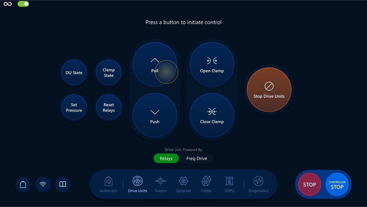
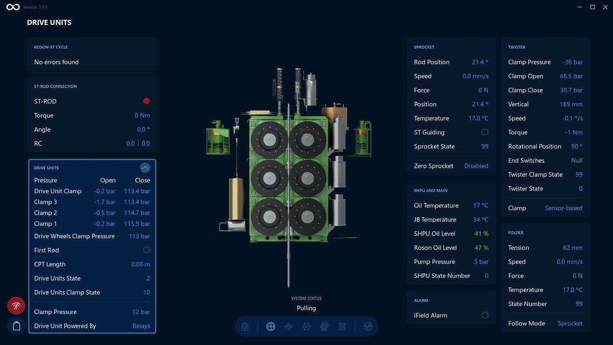
Operator can stop the process by tapping the Controlled Stop button on the bottom right side. The cycle is terminated after the Controlled Stop command executed.
Open and Close Clamp
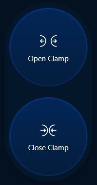
Are responsible for opening and closing the drive wheels clamp.
The buttons:
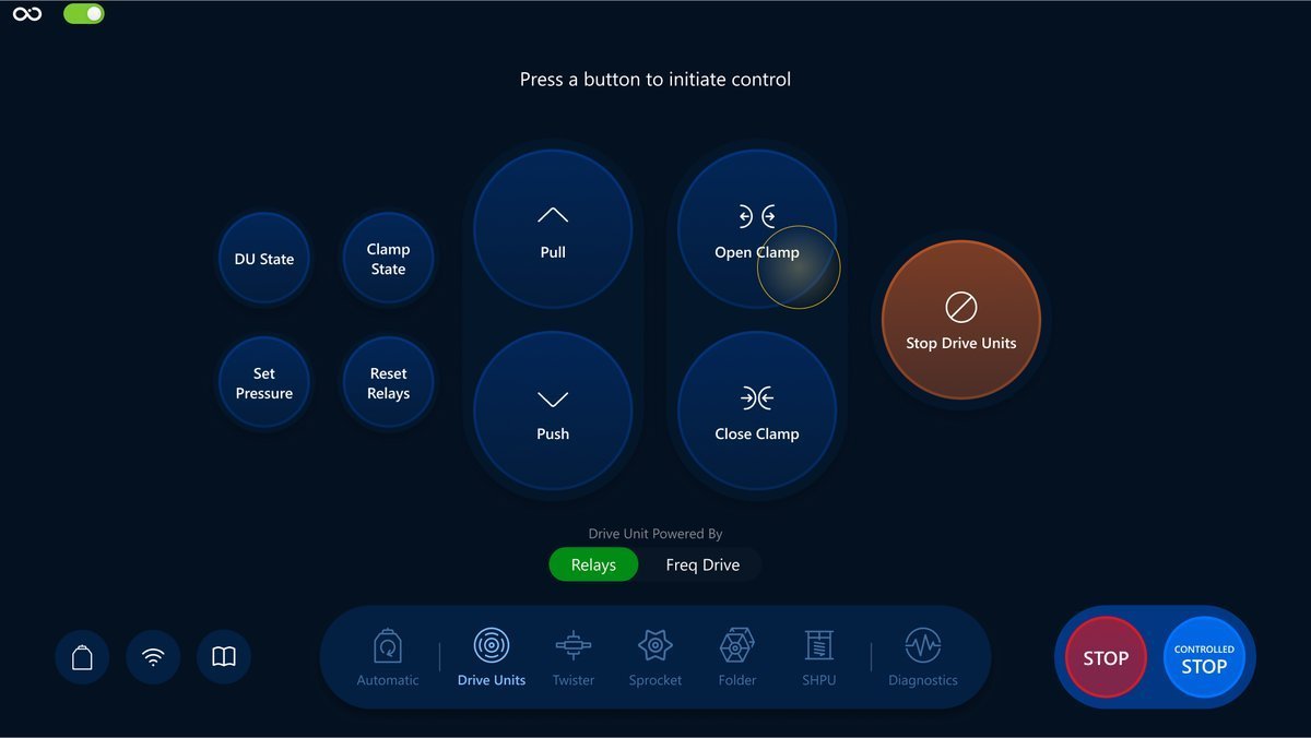
An example of the Visualization screen after Open Clamp button is pressed. We can see the values changed:
Open Clamp:
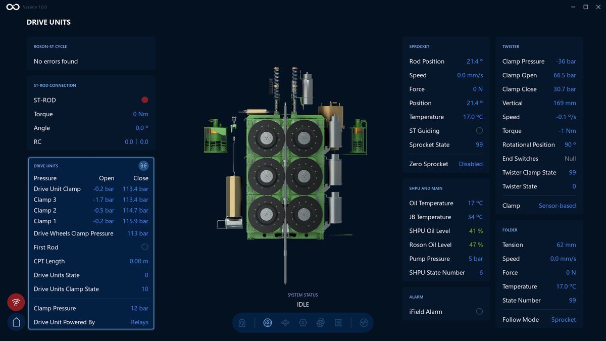
Close Clamp:
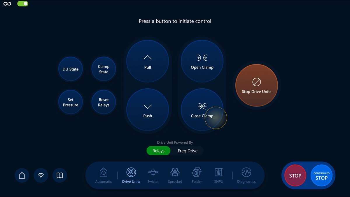
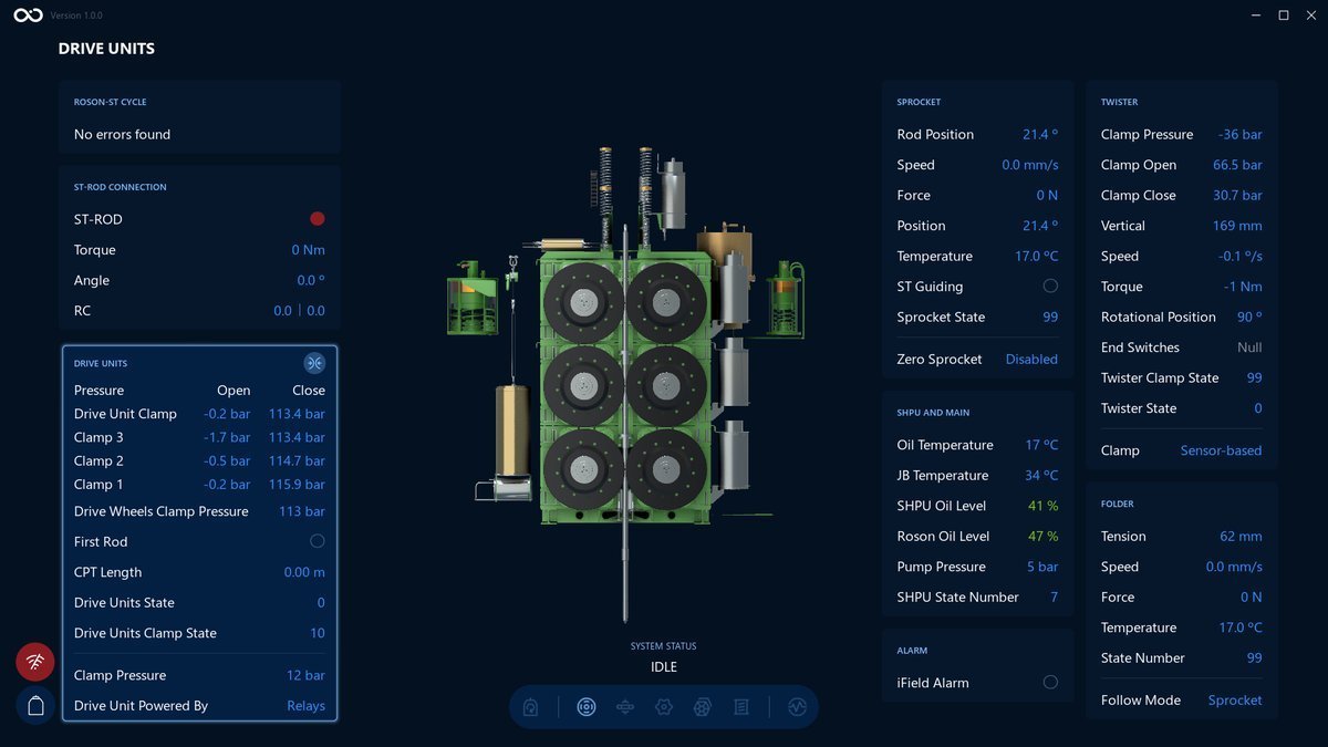
Tap on the Controlled Stop button to stop the process.
Stop Drive Units
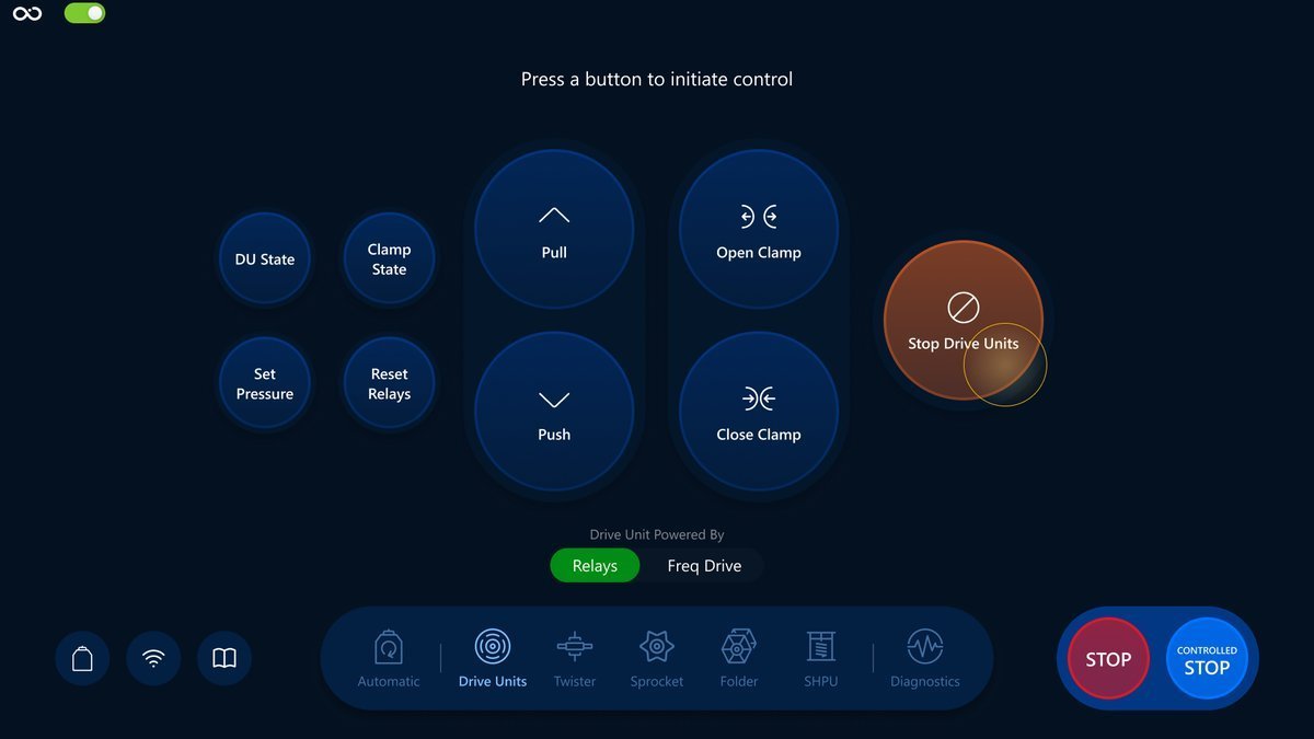
Tap to execute the command for Stop Drive Units.
The button:
An example of the Visualization screen after Stop Drive Units button is pressed. We can see the system status changed. There's no visible difference in the Visualization screen itself when Stop Drive Units is executed, other than the Drive Units no longer pushing/pulling:
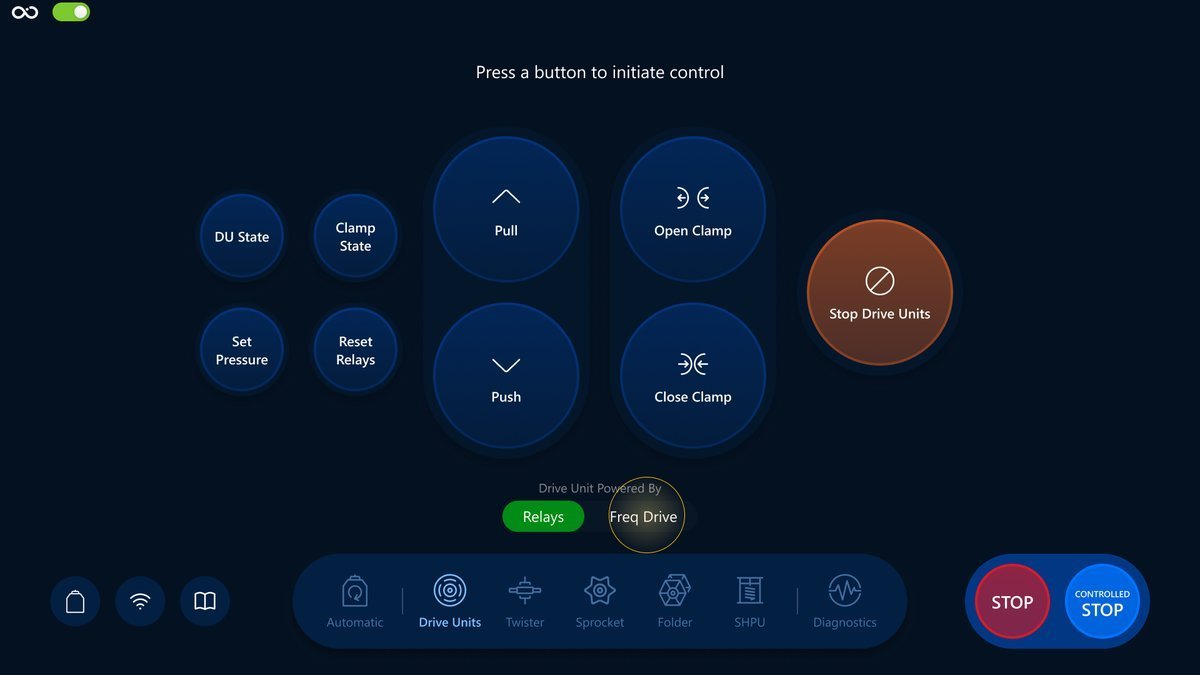
Drive Unit Powered By
Tap to switch between Relays and Freq Drive modes.
The switcher:

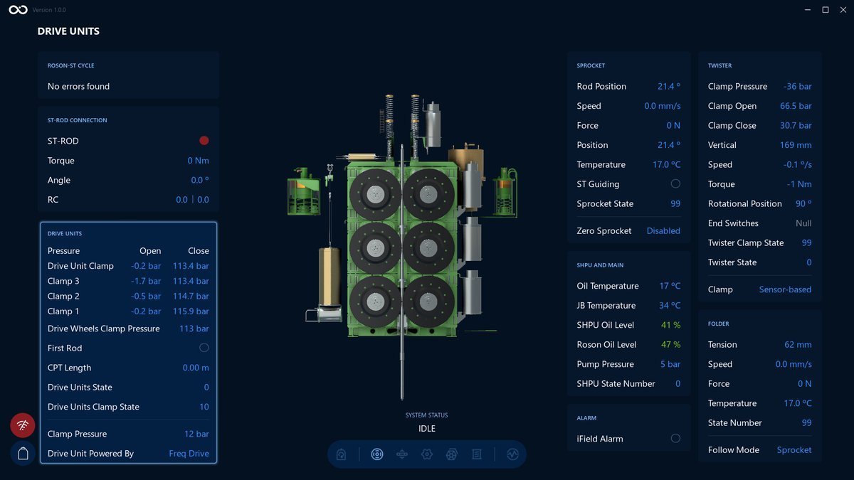
An example of the Visualization screen after Drive Unit Powered By switched to Freq Drive. We can see the Drive Unit Powered By has changed on the bottom left side:
When Drive Unit Powered By switched to Relays, Diagnostics: Drive Units tab is disabled.
What's next?
Feel free to go to the next section and learn the Twister controls in a more detail: Twister overview